We are offering a complete set of 3D positioner & accessories required for antenna positioning for far-field pattern plotting. As against rotary tables which have been the common practice, we offer state of the art 3 D positioner for research and development & measurement in antennas. It provides freedom required for antenna pattern measurement. One is able to hold the antenna from the back lobe and rotate the antenna by 360 degrees along a horizontal plane for azimuthal measurements. Over 360 degree of rotation in a vertical plane is used for elevation plane measurements. The stepper motor controlled rotator is controlled by PC using software provided. The data acquisition system software controls the axis motors and synchronizes the VNA to record the RF level corresponding to different angular locations. The data array is then used to synthesize the pattern in 3D for visualization as per IEEE norms. Low loss cables armored cables connect the Reference and test antennas to the VNA (provided by the customer). The system is able to interface to Keysight, R&S, Anritsu, Planar brands of VNA’s. A pair of planar horn antennas with calibration charts complete the measurement setup for measuring the gain of the test antenna. Pyramidal absorbers are used to shroud the antenna rotator to reduce the radar cross-section and reduce the induction in the near field. This enables the antenna to be measured in the near anechoic field and obviates the need for an anechoic chamber for >50% of antenna measurements. For R&D a quick first pass of measurement is desired for faster iterations and emphasis is mostly on the main lobe, gain, beamwidth, sidelobe levels etc. Only when the need is to characterize these with a higher order of accuracy and <-20dB sidelobe levels do we really would require an anechoic chamber.
1. Frequency support till 40 GHz.
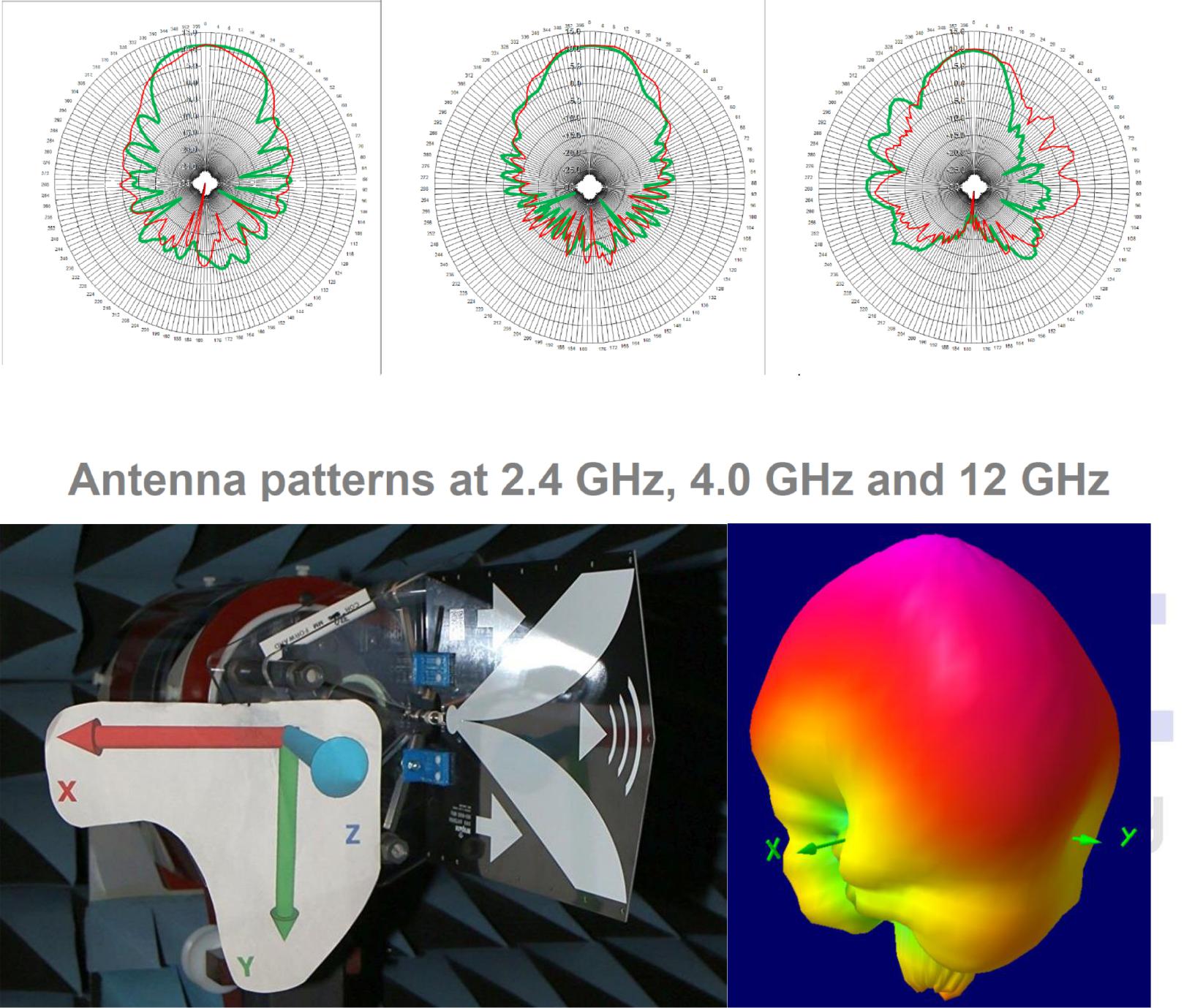
2. 3D Positioner (with VNA interfacing for Automatic Measurement of 3D pattern, gain measurement, S-parameter etc).
3. Maximum load: up to 1.5Kg.
4. Azimuth rotation: 360 degrees.
5. Elevation Movement will be 360 degrees.
6. Ultra Low loss Testing cables.
7. 3D Visualization and Data Acquisition Software.
|
Antenna Mount |
Full spherical 3D antenna mount |
|
THETA/ PHI Start/ Stop Angle |
0 to 360 degrees in 0.1degree resolution |
|
Software |
Full 3D Heat Map of with upto 12.9 million data points |
|
Hardware Compatibility |
Keysight, Anritsu, R&S, Planar VNA |
|
Software Compatibility |
MATLAB |
|
Auto Mode |
Single button operation with predefined Theta, Phi and resolution for data acquisition with motor synchronization and 3D visualization of antenna |
|
Manual Mode |
Custom Theta Start/Stop angle, and resolution Phi Start/Stop angle and resolution, with Auto stepping and Manual stepping |
|
Power |
24 V |
|
Positioner Control |
Software control via USB Cable |
|
Loading Capacity |
1.5 kg |
|
Material Finish |
Aluminum alloy |
|
Radar Cross Section |
Low Radar cross section -30dBsm |
|
Microwave Cable |
SMA-SMA cables 2m, 2-Nos |
|
Absorber for Positioner |
EM Lossy PU |
|
Foam Pyramidal Reflection |
-25dB @ 20GHz |
|
Equivalent RCS |
-20dBsm 1-40GHz |